

Building a Metal Gear Mk.II-Inspired Self-Balancing Robot (Part 2: Prototypes)
In the last post I went over my inspiration and goals for the Mk.II project. This post covers the steps I took to get the various prototypes up and running. I will be including sponsored links to the parts I purchased; if you use these links it will help me continue making content like this!
Parts
At the end of August, after getting my plan reviewed by the experts, I eagerly ordered my first batch of parts.

I sent in orders for the MCU, the motors, sensors, motor controllers, and a few other things:
- Boards
- STM32F411E-DISCO
- GM4108H-120T
- 2x SimpleFOC Mini
- 2x AS5047P Magnetic Encoder
5V Regulatornot used in current design
- Hardware
- Power
Motion Sensing
While I waited for parts to arrive, I began modelling the Mk.II in FreeCAD. I learned quite a bit here even beyond the prototyping phase, and it deserves a post of its own. Stay tuned for more on that in a later installment.
As soon as I got the STM32 board, it was time to get some coding done. I surveyed the embedded development landscape for operating systems and IDEs. What I found was that Platform.IO is pretty much the standard for embedded software, enabling a single project to target multiple boards.
I created a project but couldn’t find Arduino support for my board. I did find support for the STM32F407-DISCO board which was the previous hardware revision. I guessed they were compatible, so I moved forward with that as a project starting point. It didn’t take long before issues started to crop up, likely due to the different MCU settings between the boards. I felt I had to pivot to ZephyrOS on the STM32F411-DISCO, and luckily Platform.IO made this relatively painless:
Before:
[env:disco_f411ve]
platform = ststm32
board = disco_f407vg ;disco_f411ve
framework = arduino
After:
[env:disco_f411ve]
platform = ststm32
board = disco_f411ve
framework = zephyr
The first prototype I wanted to create was something that could display the state of the accelerometer. This was very straight-forward in Zephyr, taking only a few minutes to implement:
static const struct device *const accelerometer = DEVICE_DT_GET_ONE(st_lis2dh);
...
IMUReading reading;
sensor_sample_fetch(accelerometer);
reading.accelerometer[0] = sensor_value_to_double(&val[0]);
reading.accelerometer[1] = sensor_value_to_double(&val[1]);
reading.accelerometer[2] = sensor_value_to_double(&val[2]);
Combined with a basic led_service, this was enough to build a “this-way-up” demo:
Next, I wanted to implement something similar for the gyroscope. Only one problem: Zephyr didn’t know about the STM32’s gyroscope. It took me about an hour to figure out how to inform Zephyr about the device. I was able to reuse most of the details from the STM32F407 board configuration.
&spi1 {
    pinctrl-0 = <&spi1_nss_pa4 &spi1_sck_pa5
                &spi1_miso_pa6 &spi1_mosi_pa7>;
    pinctrl-names = "default";
    status = "okay";
    cs-gpios = <&gpioe 3 GPIO_ACTIVE_LOW>;
    i3g4250d@0 {
        compatible = "st,i3g4250d";
        reg = <0>;
        spi-max-frequency = <1000000>;
    };
};
I sent a PR so that others could benefit and then set my focus on integrating the magnetic sensors. I added an angle_service to the project that was responsible for the AS5047P sensors. The sensors support several modes: ABZ, PWM, UVW, and I²C. If you’ll recall, in the last post I received advice from the SimpleFOC forums that ABZ (aka ABI or Quadrature) was the lowest overhead. Adding this sensor to my Zephyr project as a quadrature decoder was also quite easy:
&timers3 {
    status = "okay";

    qdec: qdec {
        status = "okay";
        pinctrl-0 = <&tim3_ch1_pb4 &tim3_ch2_pb5>;
        pinctrl-names = "default";
        st,counts-per-revolution = <1000>;
    };
};
Using a cheap fridge magnet, I was able to show that the sensor was working:
A couple of times I managed to short out the system by touching the sensor power leads with the magnet’s metal housing. I didn’t realize it at the time, but this was a clear indication that my electronics hygiene needed to improve.
Motion Control
In order to wire up a full motion-control prototype, I ordered a few more things:
- 24AWG assorted colors
- DuPont Connectors
- Key Switches
- 5A Slow Blow Fuse
- Glass/Nylon Bearings
10k Resistorsget an assorted set first, replace with specific values
My first soldering project was the pair of SimpleFOC minis. The purpose of these little boards is to translate low-voltage signals (3.3v pulses) into higher voltages (~15V) sent to the motor leads.
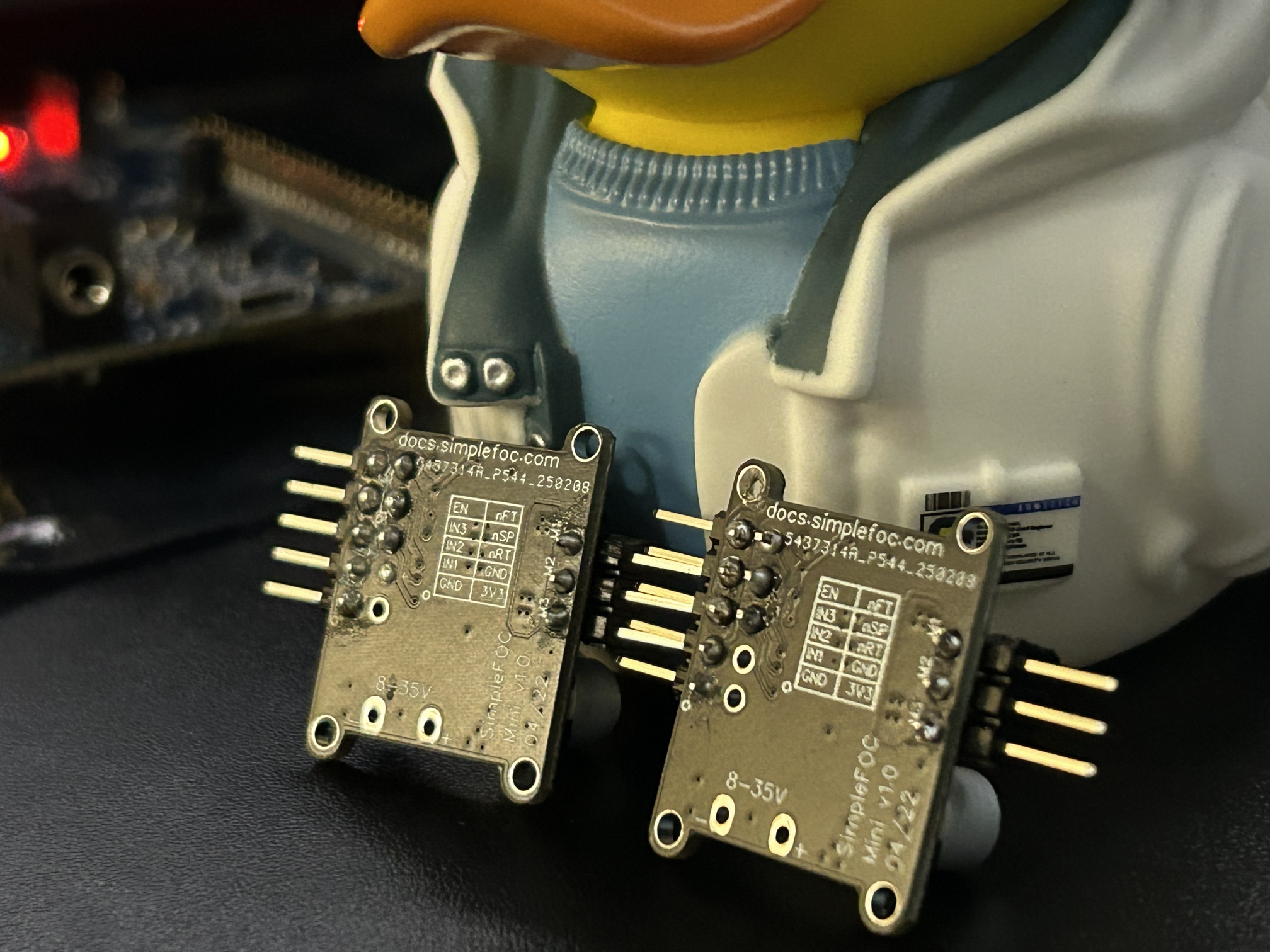
If you have any soldering experience, you can probably tell there are a few things wrong:
- Several connections have too much solder and have bulged up.
- One of the joints appears cold. (nFT on the right board)
- Flux residue not cleaned off.
Don’t worry too much about this, as I ended up rewiring this board directly and these errors didn’t impact the prototyping progress.
From the software side things weren’t simple. On one hand, I had fully working sensors under ZephyrOS, but on the other hand, I had a proof of concept in the way of the Arduino SimpleFOC Balancer project. At the time, there was only a single lonesome Zephyr project doing FOC: Spinner. I had to decide immediately whether I would attempt to fill the feature gaps to enable a SimpleFOC-like API on Zephyr or to add Arduino support for my board.
I decided, since the process to add a new STM32 Arduino variant was well documented, that adding the board aligned better with my skillset. While this did set me back several days and a couple of dollars for a CP2101 USB UART serial adapter, I do think that my contribution here has already been beneficial to the community. I wasn’t able to convince my local copy of Platform.IO to use my custom build of STM32Duino, so unfortunately I had to avoid Platform.IO for anything except serial debugging from here out.
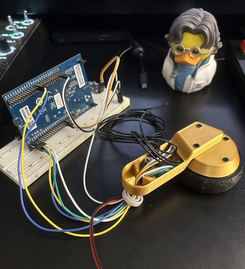
Nevertheless, after adding a motor_service I was able to get a basic SimpleFOC open-loop motion demo running:
The periodic pausing you see there is due to one out of three phases conflicting with other onboard devices. After switching the signal PWM channels to unused pins, I got smooth open-loop control working:
The Missing Magnet
I purchased some Gold Filament for the prototype. I always equip Gold in Kojima’s Games and wanted to pay homage.
 |
 |
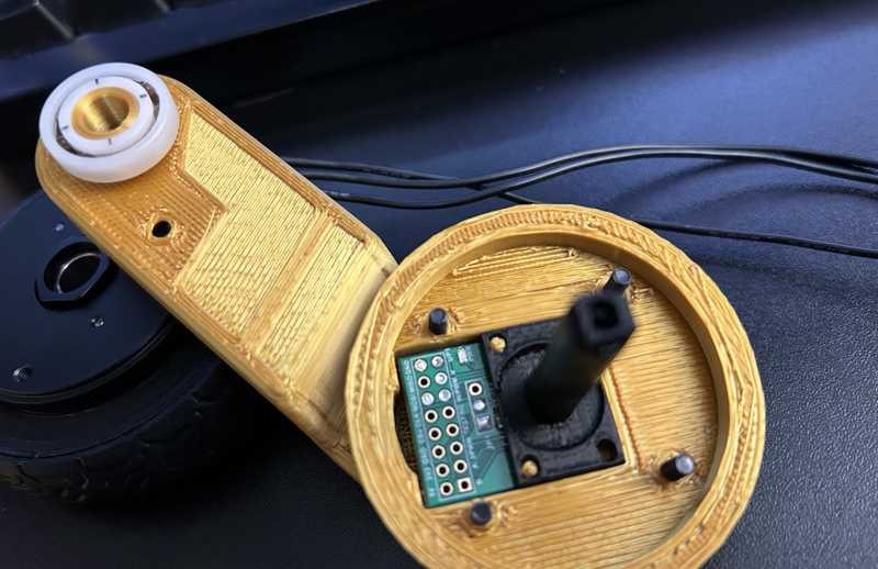
My friend Arthur was kind enough to 3D-print a few of my designs, so I was now able to integrate all of the leg parts into a single package.

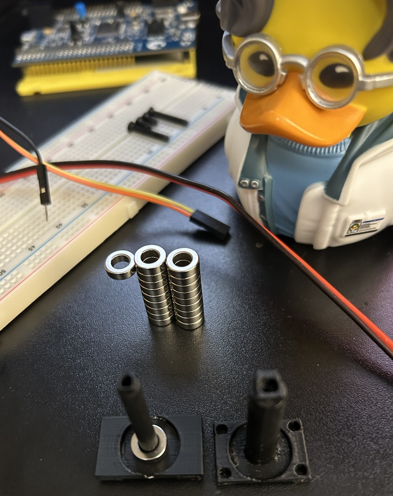
I powered up the experiment, saw the motors move, but the angle sensors read zero. I was clearly missing something. I once again implored the help of the SimpleFOC Discord channel. I had assumed that the motors’ own magnetic fields would be captured by the sensor. The AS5047P magnetic sensor does after offer the “UVW” mode, which I understood to be reading the field strength of each motor’s coils. What I did not realize is that this is merely an emulation mode offered by the chip. The chip itself requires a magnet positioned directly above it to work. And it can’t just be any old magnet either; it has to be a diametrically magnetized magnet.

If I wanted to stay true to the Mk.II/III design, I had to mount the inner wheel covers through the motor shaft. The gimbal motors I’m using have room for that, but a magnet would just block the shaft. This meant that, suddenly, I had a very very unique magnet requirement:
- Ring magnet
- Diametrically magnetized
- Small
- < ~3 mm thick
- < ~10 mm outer diameter
- As wide of an inner diameter as possible
I searched through every magnet website around but I could not find anything that fit perfectly within my original design. But, as luck would have it, I did find exactly ONE option that was close. It had a much smaller inner diameter than I like, but I wagered: with a small redesign and a change in material, I could make it work.
Once they arrived and were installed, I had every individual component working.
The Hygiene Lesson
I was still depending on my friend Arthur for 3D prints, so I figured the easiest way to get a fully integrated prototype assembled would be to build the body out of cardboard. I grabbed a cardboard box, measured up and cut holes for mounting the ankles, and threw it all together:
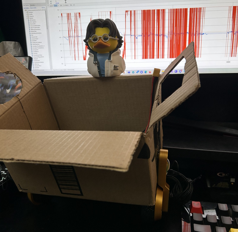
I arranged a meet-up to get the 3D printed wheels & tires at our local makerspace. And it was there that the poor electronics hygiene caught up with me. I assembled the wheels, powered the bot on, and… a twitch and then it almost immediately fell silent.
I pulled the power and hooked up USB serial to assess the damage. The board gave me random text in return. I fried the brains and the sensors. Oof. Most likely what happened is that one of the 15V leads from the step-down must have contacted one of the lower-voltage data lines on the STM32. There was nowhere to secure the voltage regulator inside the box, and I had not protected the leads.
At this point, I decided I had to make some specific changes. Going forward, I decided:
- All power leads must be sleeved.
- Any unshielded male power connector must not have power when disconnected.
- Follow standards for XT connectors.
- All power leads must be secured to the chassis.
I designed an enclosure with plenty of tie-down points and asked for Arthur to print it. I also reordered the fried parts: 1 STM32 board and 2 AS5047P sensors (all of my low-voltage devices). It didn’t take long for me to reconsider my choice of STM32. I wanted the bot to be controlled like it is in the game, and this meant using a Bluetooth controller. In parallel, I ordered a few extra parts that could be here quicker.
ESP32-S3-DevKitC-1BLE only, not used in latest design- WiFi Antenna
- INA219 Power Monitor
- 3.3V Regulator
- ICM-42688 IMU
This further hints at some design changes that we will see in later posts.
Coming Up…
In the upcoming posts, I’ll be covering my CAD journey, traction, PID tuning, designing for 3D printing, and more!
Stay tuned.
Previous Post: Part 1: System Design Next Post: Part 3: CAD Design