

Building a Metal Gear Mk.II-Inspired Self-Balancing Robot (Part 3: CAD Design)
FreeCAD
When I started the Mk.II project, I didn’t have any meaningful CAD experience. I had been watching channels like Maker’s Muse, Wintergatan, BPS.space, and rctestflight do amazing things with CAD, so I had some idea of what to do. I chose to learn FreeCAD because of its open-source nature and fully-featured user experience. In order to get up to speed, I made use of the FreeCAD 101 series on YouTube as well as Mangojelly’s videos:
- FreeCAD 1.0 Tutorial for beginners 2025
- FreeCAD: Sketch on Curved Surface
- Complex Extrude from a Single Sketch
- How to Split Solids in FreeCAD
These tutorials helped me learn the UI idiosyncrasies and the specific features I needed in order to model the Mk.II. I was able to recreate a relatively accurate model of him over the course of a couple of months.
This is not to say that the journey was easy. FreeCAD has two really big issues that cause user friction:
- Edge/face renames break history & sketches
- B-splines get introduced for linear features by some operations.
These issues will absolutely break your workflow if you don’t plan around them. I have managed to find workarounds that avoid these issues wherever possible.
Dodging FreeCAD Roadblocks
Master Sketches
The first strategy that I want to share is the use of Master Sketches. FreeCAD’s operations, like Pad, Pocket, Groove, etc. operate on the selection they are given. To put it another way, you can select part of a sketch in order to limit the operation to that part. For example, take this simple shape:
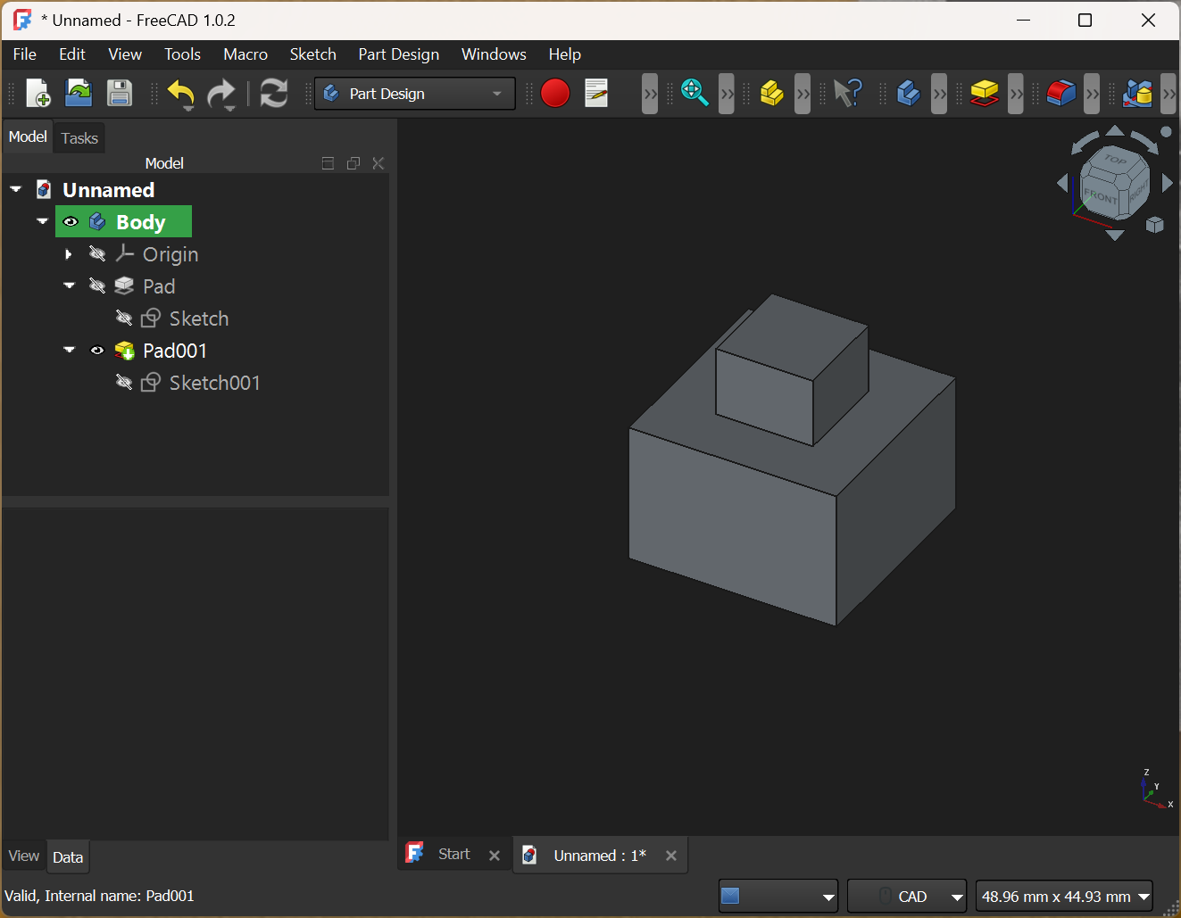
The most straight-forward way to construct this is by Padding (extruding) with a sketch drawn on the top face, like this:
This works well if you are using absolute measurements everywhere. However, as soon as you need constraints between e.g. the larger block and smaller one, then this strategy would have you depending on specific edges and faces of the output geometry. Output geometry can and will change as you are iterating on a design, so this is a shaky foundation. You will end up breaking the references that you constrained your sketch to.
A better solution is to put as many of the shapes and constraints into a single sketch as you can. Then, only one sketch drives the outputs of your object, and each feature is independent of the output geometry of the others.
Note that both Pad operations in this example refer to the same sketch. Destructive operations such as deleting sketch edges will still potentially lead to broken geometry, but all additive modifications to the sketch will apply without breaking any unrelated geometry. This turns out to be a specific form of my next strategy.
Refer to the earliest geometry possible.
The main benefit of Master Sketches is that they automatically force your operations to refer to the earliest possible feature (the Master Sketch itself). Since none of your operations rely on the outputs of any others, they cannot break each other’s constraints. This can be generalized to situations where a single sketch is not sufficient.
If you must base a feature or sketch on output geometry, reference the earliest instance of that geometry whenever possible. In particular, avoid referencing the output of chamfer and fillet operations, preferring to reference the unmodified faces from the previous feature tree item.
Use Clones and the Part Workbench
Cloning or shape-binding a Master Object is another way to ensure your feature tree stays linear and short. If you have two parts that interface in some way, creating a single Master Object and deriving both parts from that will prevent your tree from getting tangled.
In addition, several operations in the Part Design workbench do not allow access to modify earlier features in the feature tree. Namely the boolean operations and the Hole operation as they “consume” the previous node in the feature tree. There are two strategies to avoid getting stuck, unable to modify those past objects.
The first option is to always clone your object before performing a boolean operation in the Part Design workbench. The clone will track changes to the “tip” of the object it references, allowing you to make changes to that node that propagate.
The second option is to use the Part workbench to do the boolean operation and then converting the object back into a Part Design body. This option is my preferred way of working as it keeps the feature tree a bit more tidy.
Having both of these options available has helped me work around a few bugs, so it’s good to keep both in mind.
Don’t Reinvent the GM4108H-120T
I purchased several off-the-shelf components for my bot. While I might eventually design my own board, for the prototypes I chose to use single-purpose module boards and dev kit boards. These have the advantage of being well documented. This usually means that there are CAD files with the exact part dimensions already available online. The motors I chose are also a very standard entity. Because they are being used for drones and other robotics projects, the CAD files for them have been released as well.
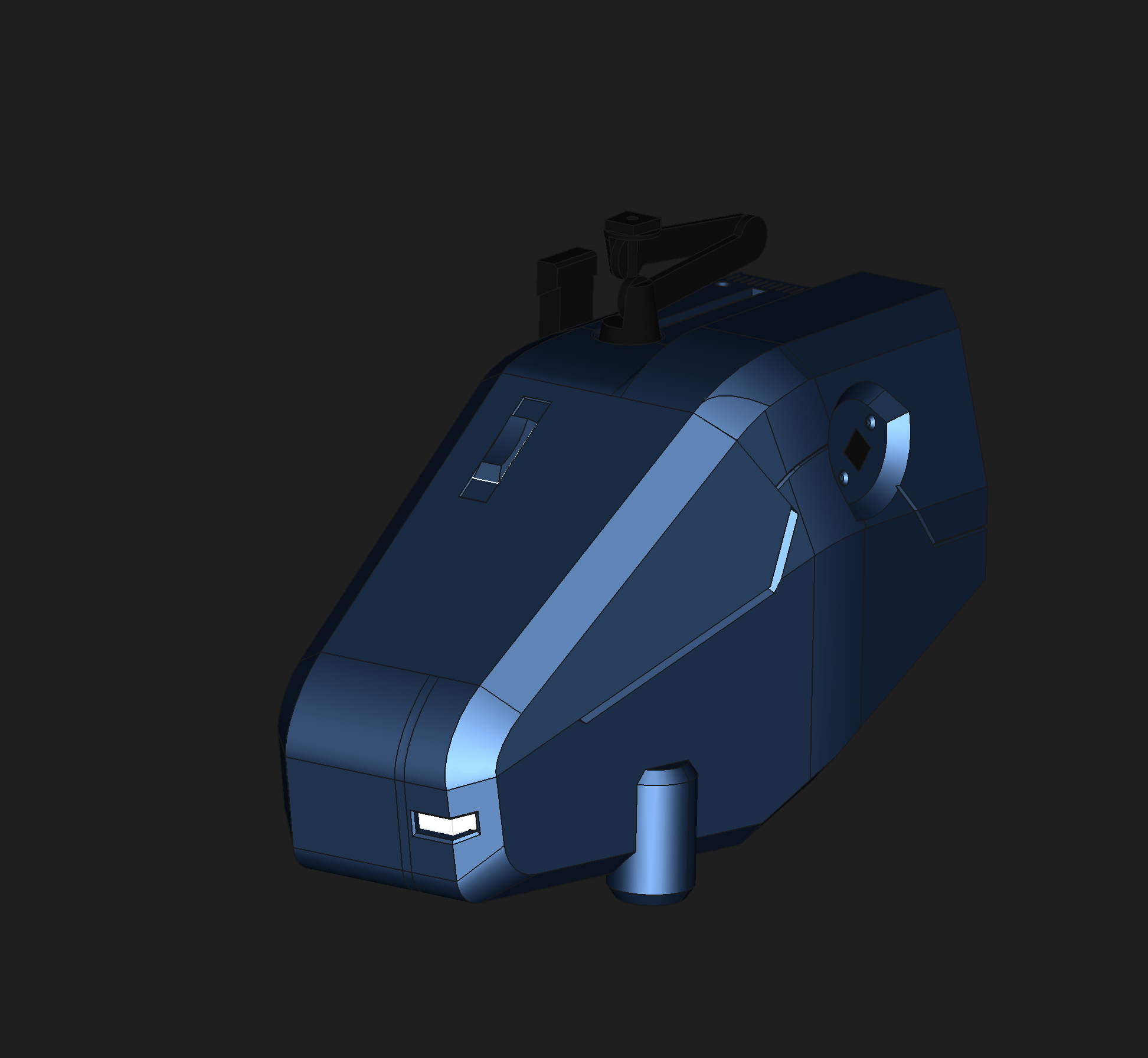
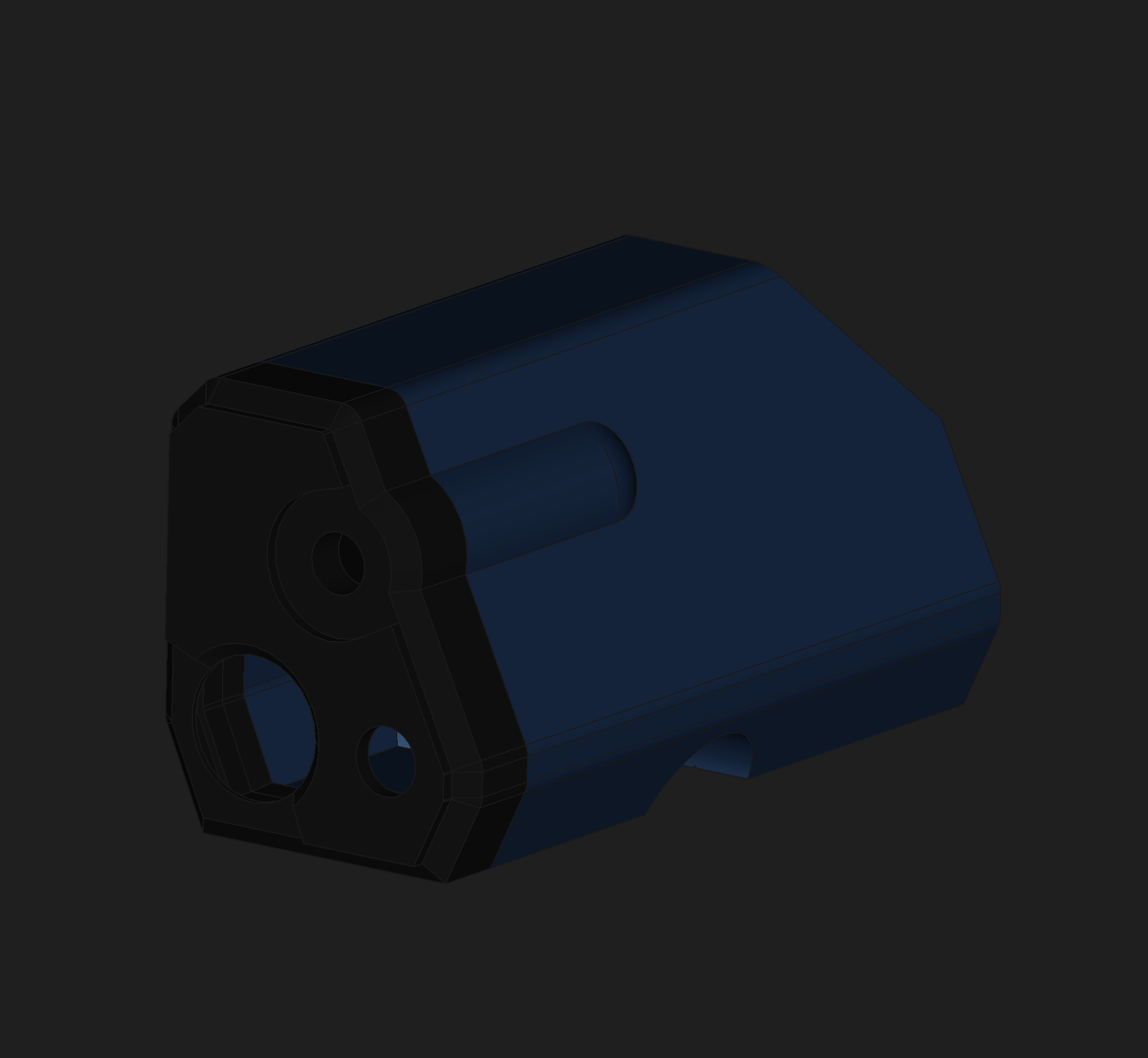
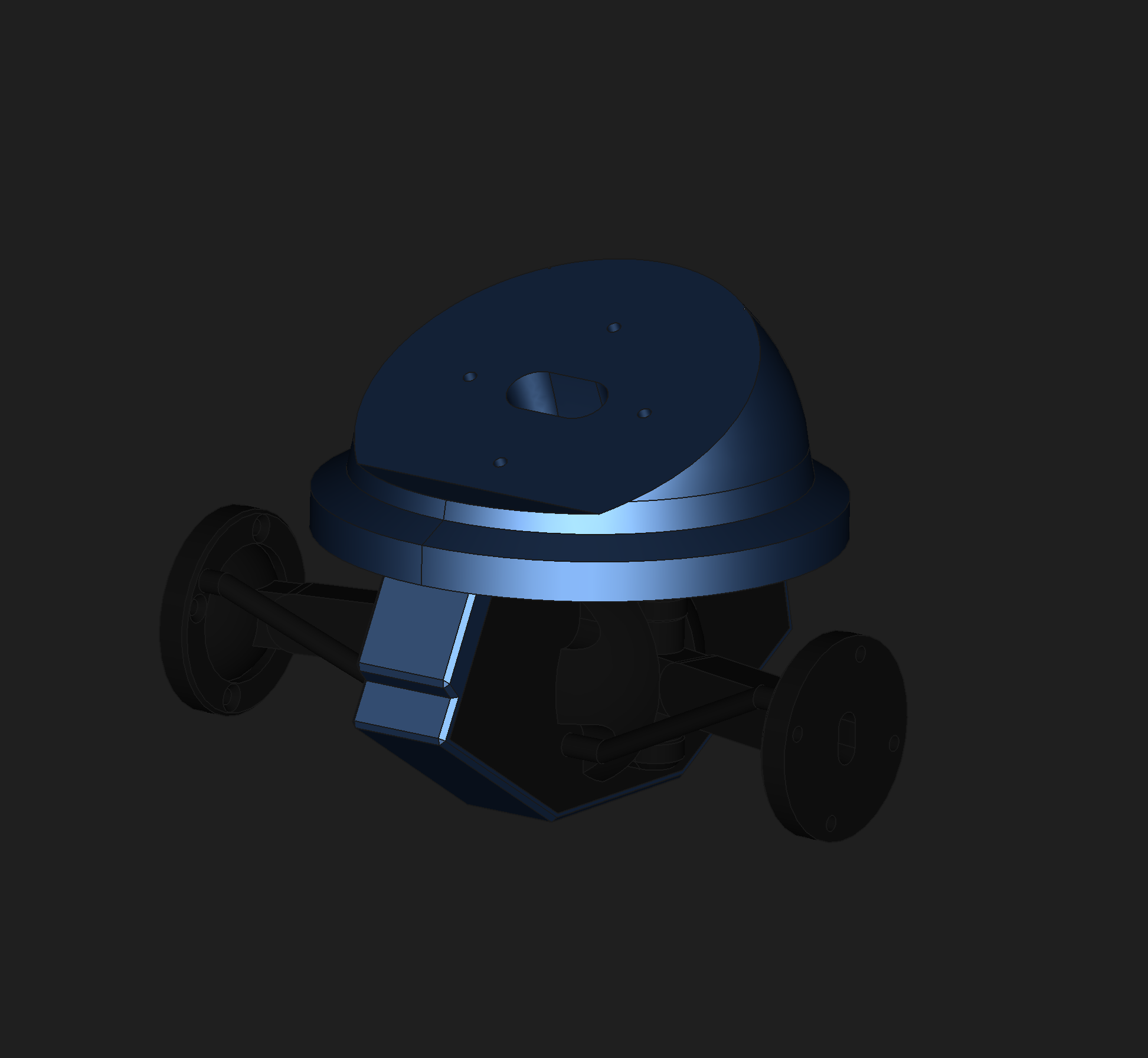
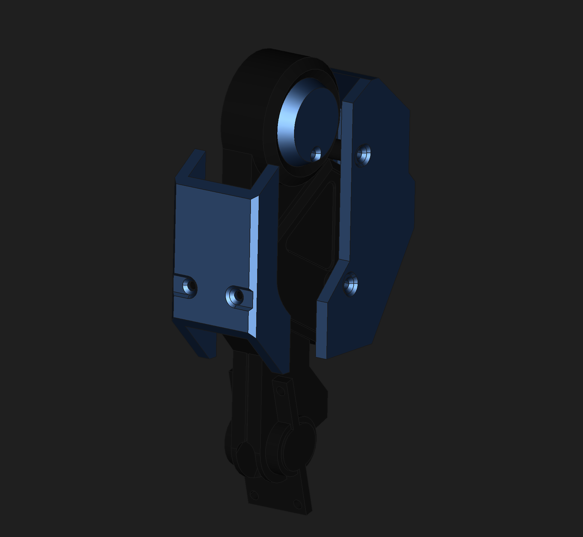
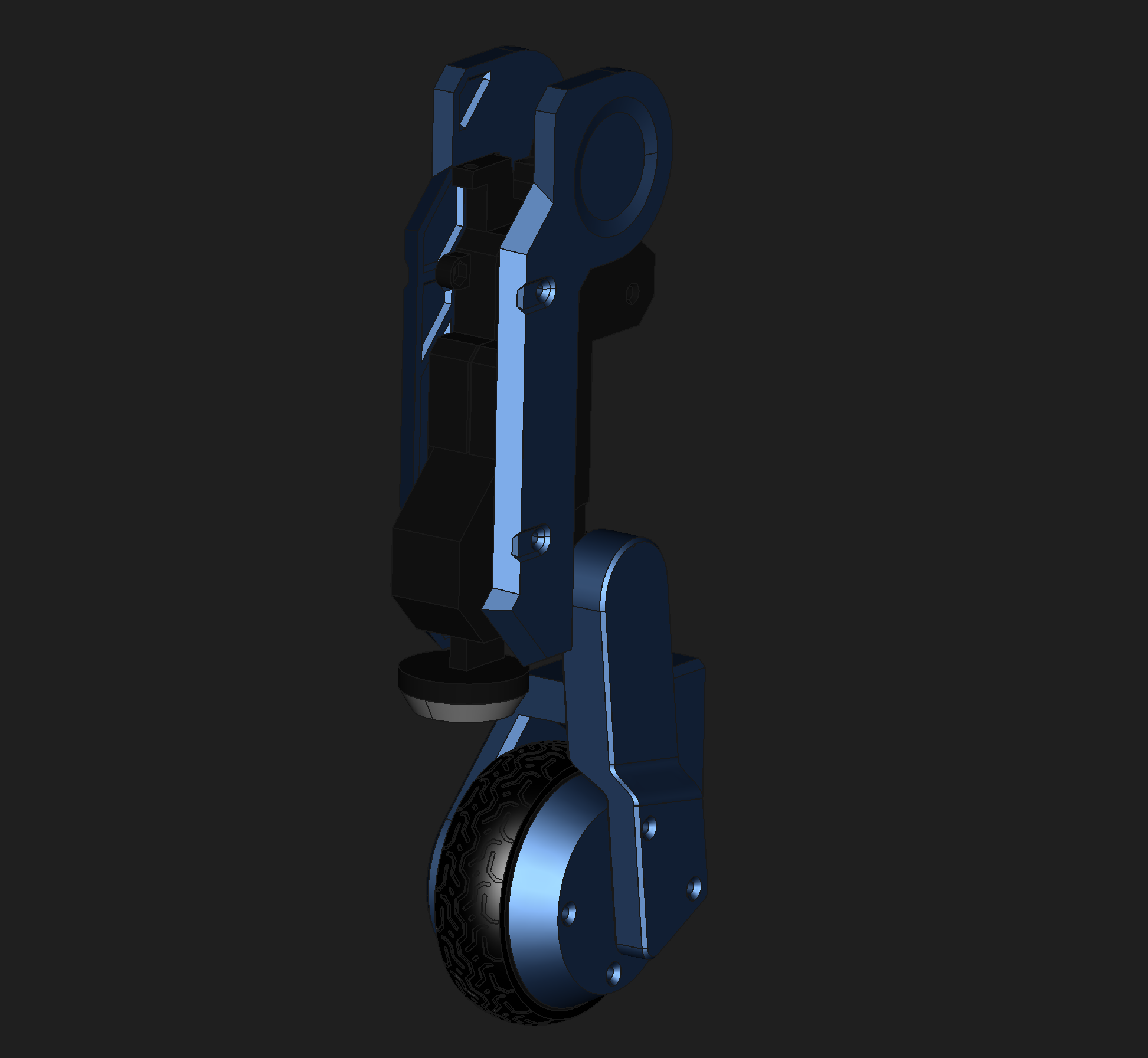
Several of the components I purchased didn’t have existing CAD models. Rather than design them into the Mk.II, I chose to design separate models and import them:
I used these reference models as Master Objects via clones and shape-binders to drive the interfaces between them and the bot. But just using the parts alone was not enough to guarantee things fit.
Designing for 3D-Printing
Parts Have Layers, Like an Ogre
3D printers typically produce objects with horizontal layers. There are, of course, exceptions including belt-fed printers and unconstrained toolpath generation (like https://www.gerridaj.com/ or https://fullcontrol.xyz). But even in these cases 3D prints tend to have weakpoints due to layer adhesion.
These implicit weakpoints necessitated design consideration. For each of my parts I applied this simple process to work around these weaknesses:
- Determine the limits of stress that the part will experience. Make particular note of tension and shear stresses. Layer adhesion is typically not a problem for compressive stresses.
- Plan the layer lines so that the solid filament lines are parallel to the stresses.
- Incorporate a large, flat area on your part parallel to your layer lines. You will print with this area on the bed, minimizing support.
- If there is no flat area, plan to slice the part in half and join them. I primarily used screws as fasteners, but also included a couple of snap-fit interfaces.
- If multiple flat areas are available, choose the one that will result in the most visually appealing layer lines, followed by the one that uses the least support material.
- Proceed to design your part, applying clearances according to the accuracy of your printer in each dimension.
During the export of any 3D model to FDM G-code, curved edges will get turned into small line segments. This means that any curved surface will have a slightly smaller radius when printed. Also, since 3D printers cannot draw lines significantly narrower than the nozzle width, corners are always rounded.
To compensate for this, clearances need to be added on faces and corners where parts fit together. For my X & Y axes, I used a quarter of my nozzle size (0.1mm) on each face. When adding up the left and right sides, this means I am allowing a total deviation of one-half of a nozzle.
Zero clearance will almost never work, even for snug fit parts. Only the strongest parts can withstand assembly with no clearance.
One thing I learned late in the process was the use of variables. I wish I had introduced a variable for my clearance early on in my project, so please learn from my mistake and use a Variable Set for your printer tolerances, etc.
Watch Your First Layer
The first layer of any 3D print is the most critical. If the filament doesn’t stick to the print bed, your part will not take shape. In contrast, if your first layer prints perfectly, the rest of your print is very likely to succeed (overhangs & bridges notwithstanding). So, the advice you will hear time and again is to always watch the first layer. I can attest that this is the best way to avoid wasting time and material on a print that is doomed to fail.
Coming Up…
If you read up to this point, you’ve seen the process I used to design the Mk.II’s various components. Coming up is where the rubber meets the road (literaly!). We’ll be talking traction, balance, PID tuning and finally showing off the bot!
Previous Post: Part 2: Prototypes Next Post: Part 4: Traction and Balance