

Building a Metal Gear Mk.II-Inspired Self-Balancing Robot (Part 4: Traction and Balance)
Iterating on a Tire Design
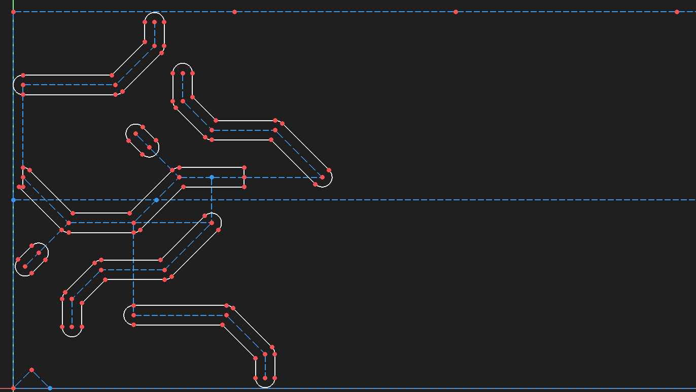
The game designers for the Mk.II added a distinctive tread pattern to the wheels, and to me it looked both functional and visually appealing. The tread’s angular pattern resembles a circuit board which is quite fitting to the personality of the bot.
In order to replicate this pattern, I had to make use of the 3rd-party Curves Workbench in FreeCAD. This feature projects curved surfaces onto a flat sketch, letting you use familiar tools and constraints. Surprisingly, this turned out to be one of the easiest tasks on the bot, thanks to the simplicity of the workbench.
The first version of the tire was printed with basic slicer settings in TPU. I expected TPU’s softness to aid in traction, but I immediately learned that it was simply too smooth to get anywhere. There was, however, one slicer trick I knew I could try: fuzzy walls.
The first of my working prototypes used these fuzzy-walled tires. While they absolutely improved performance, they still did not have very much traction on hard surfaces (even slightly rough ones). Only on carpet did this iteration have anywhere near enough traction to balance its weight.
My friend Arthur, who printed the whole first prototype for me, shared a trick he used in combat robotics: coat the wheels with latex paint to give them extra traction. This worked, but it wore off far too quickly. Arthur also encouraged me to join him at a couple of his robotics competitions, and there I met someone who shared a solution to this problem using urethane rubber casting.
Molding
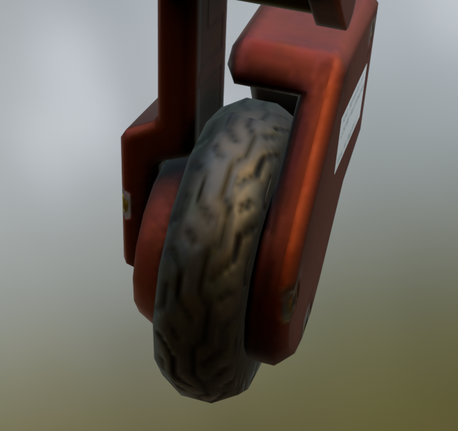
From the combat robotics meetup, I learned that designing a tire mold was pretty easy: subtract the tire from a solid block and slice it into 4 parts. I grabbed some 30A Hardness urethane and, due to the complex tread pattern, I chose to purchase some mold release as well.
I secured the wheels into the center of the molds, screwed them down, and poured the rubber.
The final iteration of the wheels came out great. The sprues (extra bits) were easily cut off by passing a hobby knife between the lid and the rest of the mold. The rubber tires have performed well on a variety of surfaces, both soft and hard. With traction solved, the next challenge was stability.
Balance Logic
Getting a bot to balance is theoretically straightforward. Similar to a car in cruise control, it’s largely a problem of controlling a single variable. In the case of the car, the variable would be the speed; for the Mk.II, it is the pitch angle. PID controllers are a very common way to do this since they model many types of problems reasonably well. PID controllers relate the difference in the target variable to some other output, such as throttle or torque. Their robustness comes from their use of the “present” (the Proportional term), the “past” (the Integral term), and the “future” (the Derivative term).
In practice, optimizing only a single variable won’t work without precise calibration. So, we have to control an additional variable: the target pitch angle. If our robot drifts to one side or another, we can use a second PID controller to adjust the target pitch in the opposite direction.
This turns out to be sufficient to get the bot to balance. Here are some resources to learn more about this specific arrangement and PID tuning in general:
Dual Board Control
Having seen good results with the small-scale prototype, I began putting together the full-sized bot. Still, the testing showed some issues that needed to be addressed. The ESP32-S3 only supports BLE (Bluetooth Low Energy) but all of the controllers I wanted to use needed Bluetooth Classic. In addition, the IMU I had purchased gave incredibly noisy data but only intermittently.
I purchased an ESP32 DevKit v1 and tested it with the small scale prototype. While it looked like it would have the specs needed to run the bot, it turned out to be very difficult to get a 1khz control loop to run smoothly. This seemed to put me in a worse position at first, but I realized that I had written-off a perfectly good solution: using two boards together.
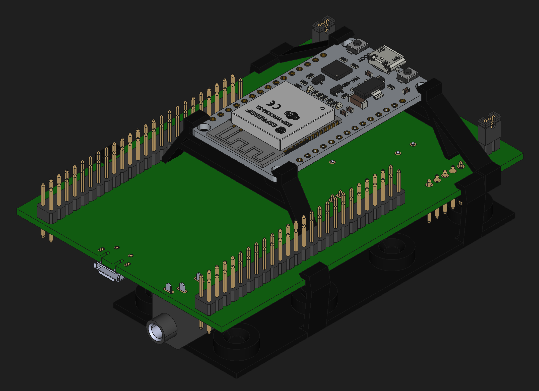
Using both the STM32 and ESP32 allowed me to leverage their individual strengths. My STM32 Discovery has an onboard IMU and the performance needed to run the balance control loop. The ESP32 can asynchronously communicate with many clients at once: Bluetooth, WiFi, UART, etc. I chose to use lwpkt on top of UART to frame messages between the boards and to reject bad packets.
Assembly
With the decision to use two microcontroller boards came the requirement to mount them securely. I designed a set of lightweigth brackets to hold the boards together.
The Mk.II model in game has a back-panel that resembles a 1990’s camcorder. On the back, it says “整備ケーブルコネクタ口 ケーブルが挿す上下が気を付けろ” which Google tells me means “Maintenance Cable Port: Pay Attention to Connector Orientation”. While I’m a stickler for details, I decided that USB-C Panel Mount connectors would be acceptable. These were connected as the boards were installed with the help of a couple of adapters:
I also added an external USB-B cable to represent the Mk.II’s “tentacle.” In the game, he uses it to manipulate both objects and computers. While I don’t yet have the ability to make a prehensile arm, I was able to give him mild hacking abilities.
Phantom Vibration
Once fully assembled, however, the Mk.II developed an odd vibration. I first suspected this to be caused by excessively high PID coefficients.
However, no amount of tuning could remove the oscillation. After chatting with the folks in the SimpleFOC discord again, I learned that the actual source of the issue was the placement of the accelerometer away from the center of rotation. My decision to pivot to the STM32 Discovery board placed the IMU several centimeters above the center of mass.
@copper280z told me that, in a configuration like this, the accelerometer will feel forces from rotation which it cannot distinguish from gravity. While this made sense, I was intrigued to learn that the effect can be subtracted out using the gyroscope if the exact distance from the center of rotation is known.
At the time, I did not have the gyroscope working. I had to debug the Adafruit library to add support for the onboard IMU. If you see the Adafruit maintainers, kindly ask them to look at my pull request.
I was able to reduce the vibrations to a small jitter by estimating the offset and subtracting out a centripetal term. It seemed that fully eliminating the effect would again require precise calibration. I chatted with Art from robomates about how he solved this problem for his bots. He said that his DMP IMU solved it for him.
After a bit of searching and a bit more chatting with @copper280z I finally learned what to do. The final trick to get rid of the vibration was to use the gyroscope as the primary source of pitch information. This can only happen after finding an absolute “down” direction with the accelerometer. I implemented this for the Mk.II using a complementary filter weighted 98% to the gyroscope. This completely eliminated the vibration while still allowing the accelerometer to provide long-term stability.
Coming Up…
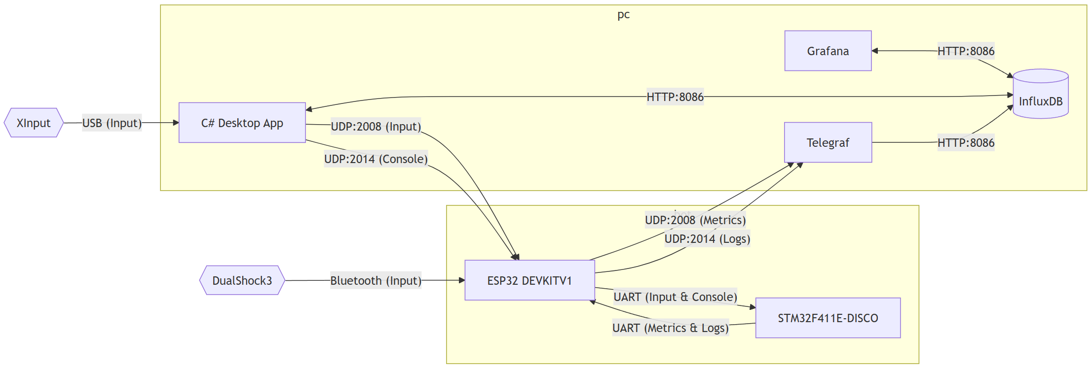
In the final post, I’ll show how to control the Mk.II in real time, along with the telemetry and tooling I use to debug it while it’s running.
Previous Post: Part 3: CAD Design